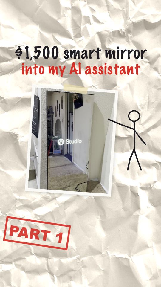
$1,500 smart mirror
into my AI assistant
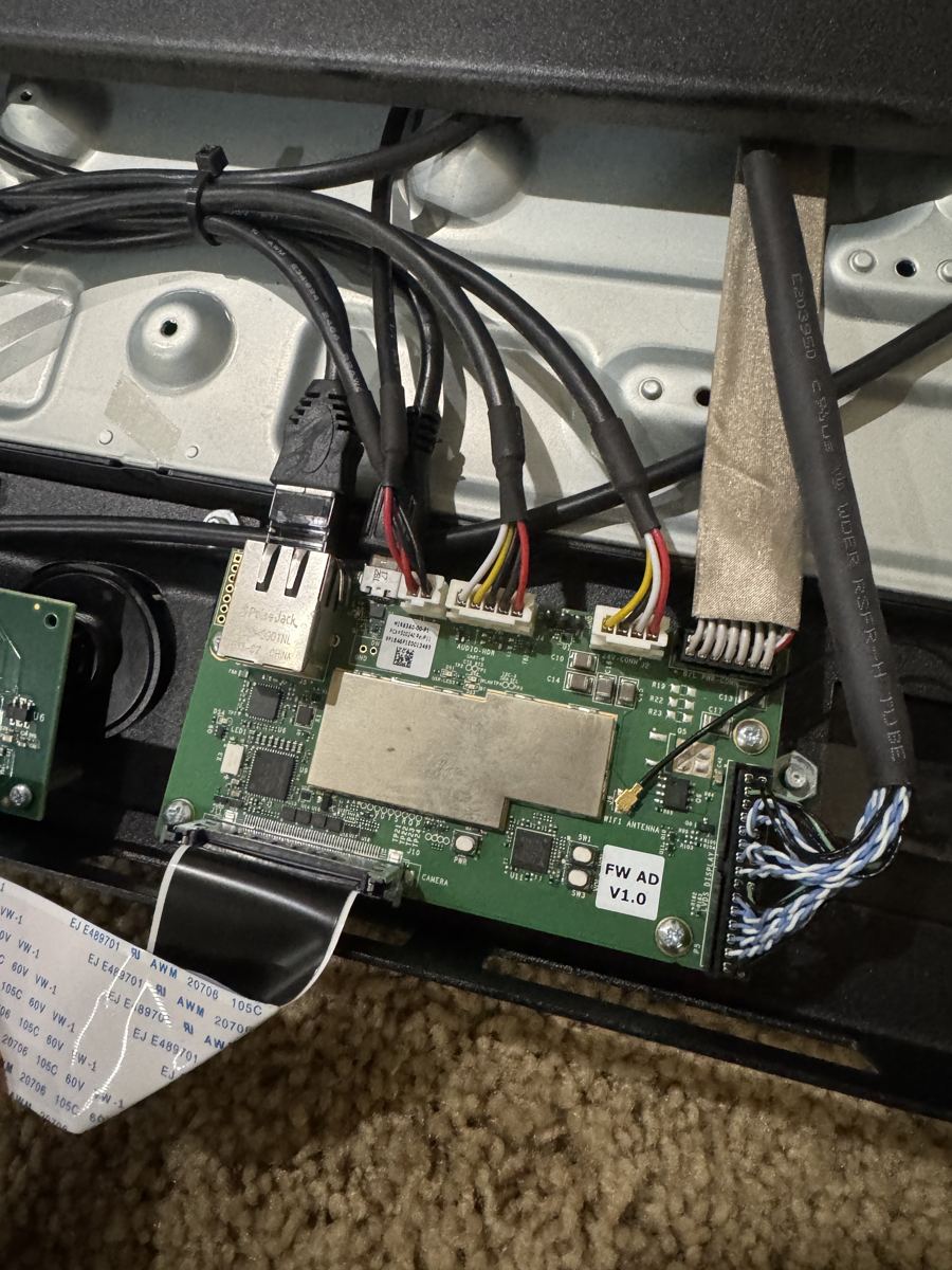
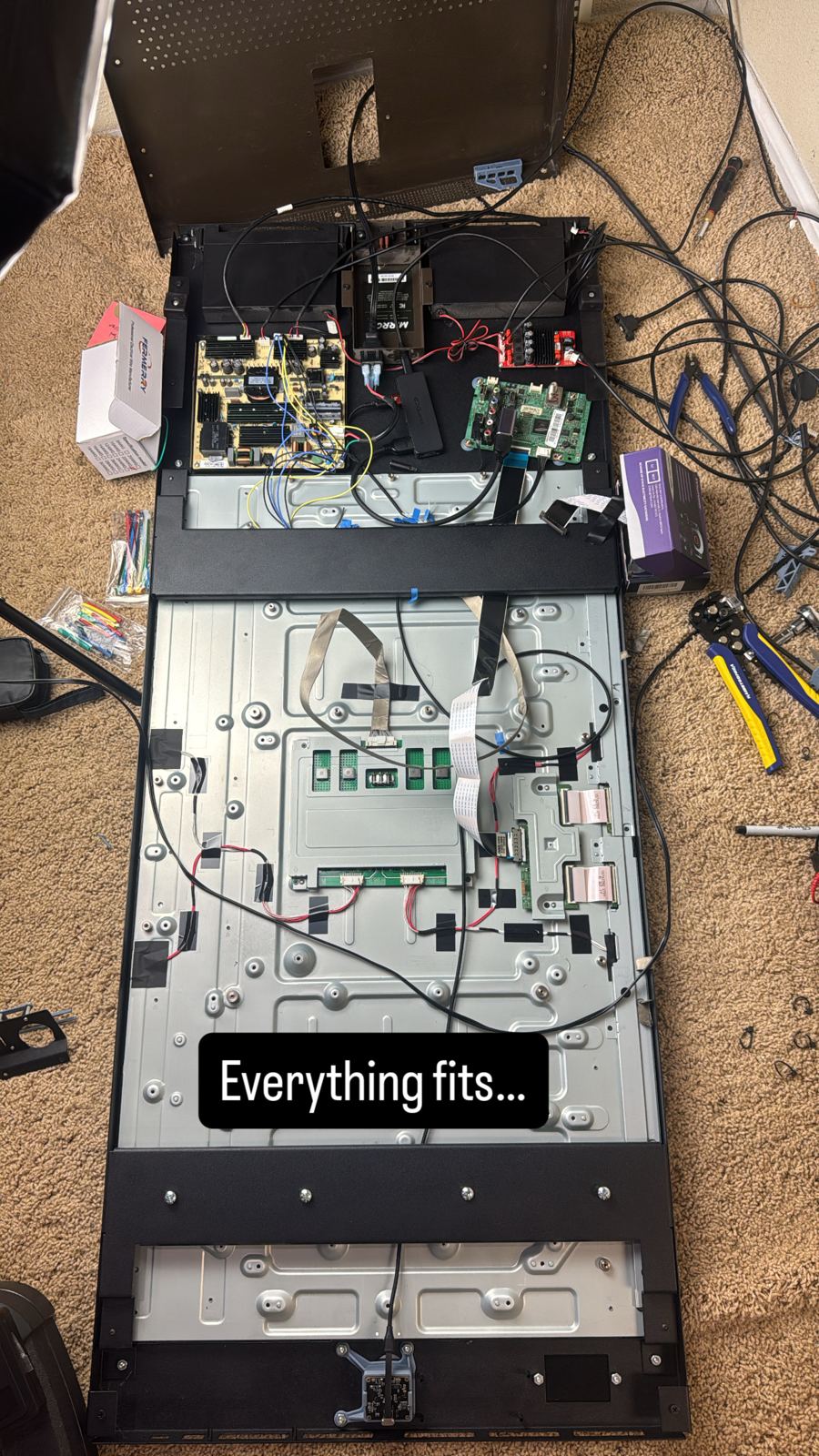
$150 Lululemon Mirror off Marketplace. New Samsung TV board, 4K camera behind the glass.
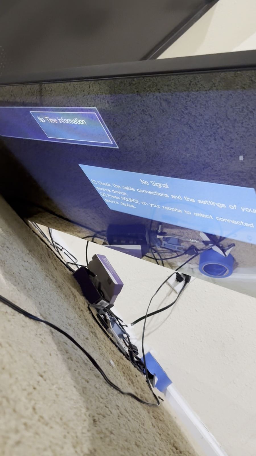
teardownthe plan14 pinswrong cablemountswiringfirst lightnext: ???
How it works
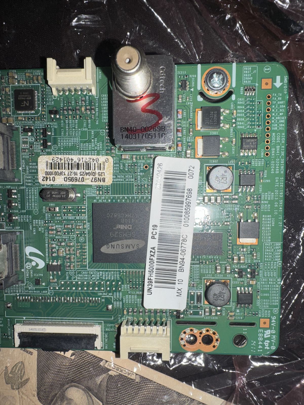
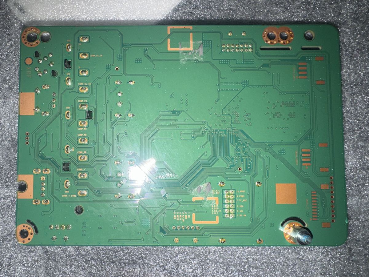
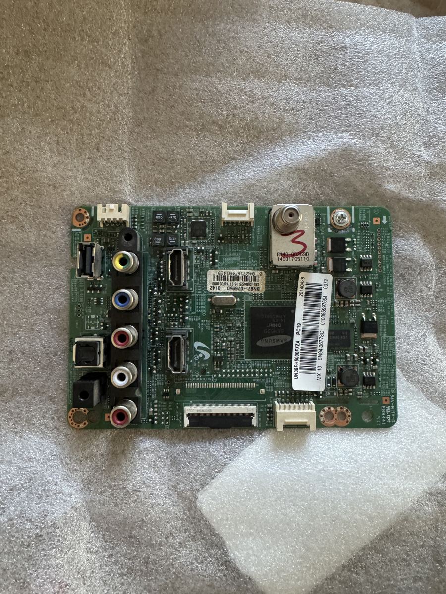
- Android board out. Samsung BN94-06778C TV board in, same panel i
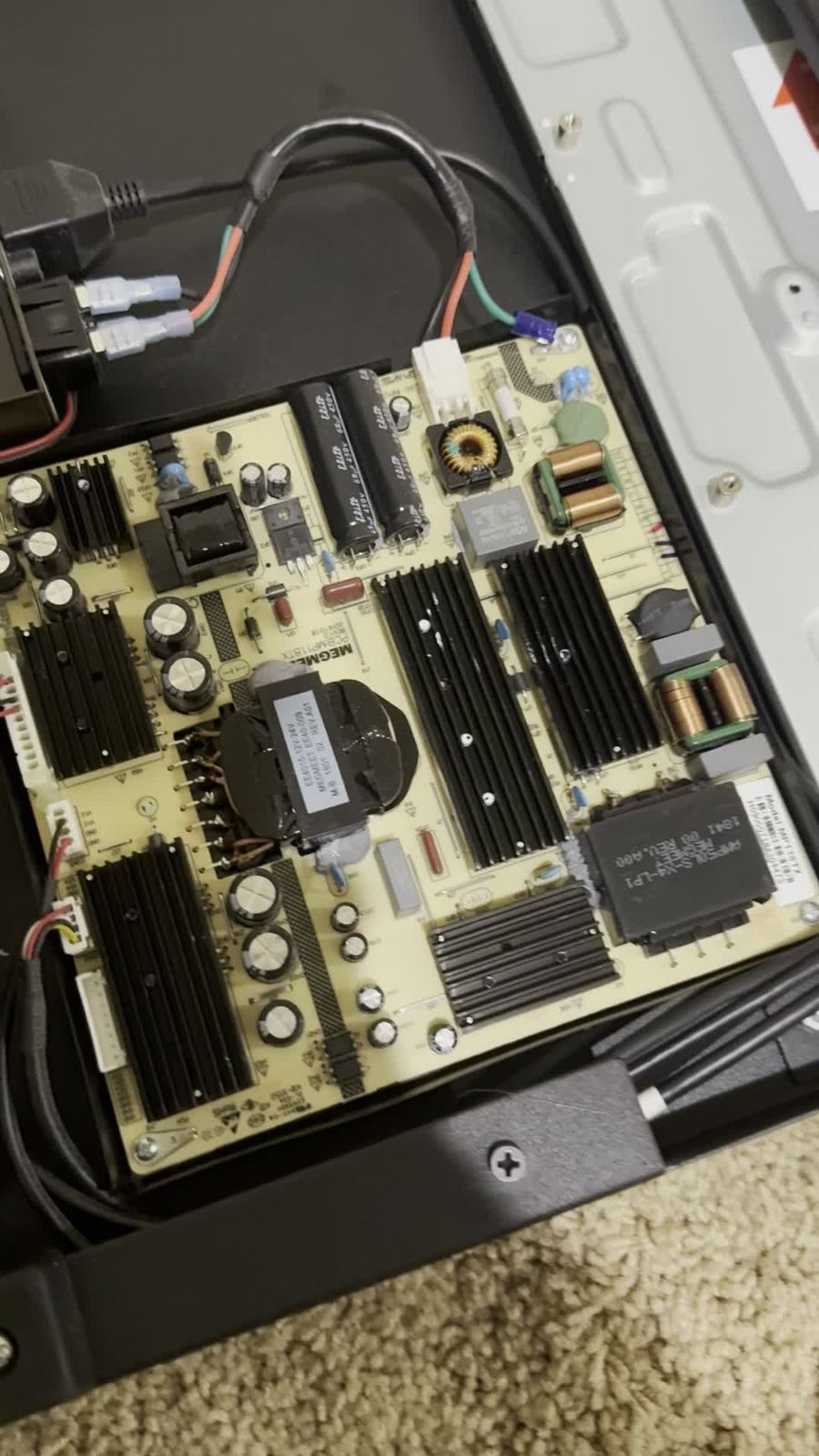
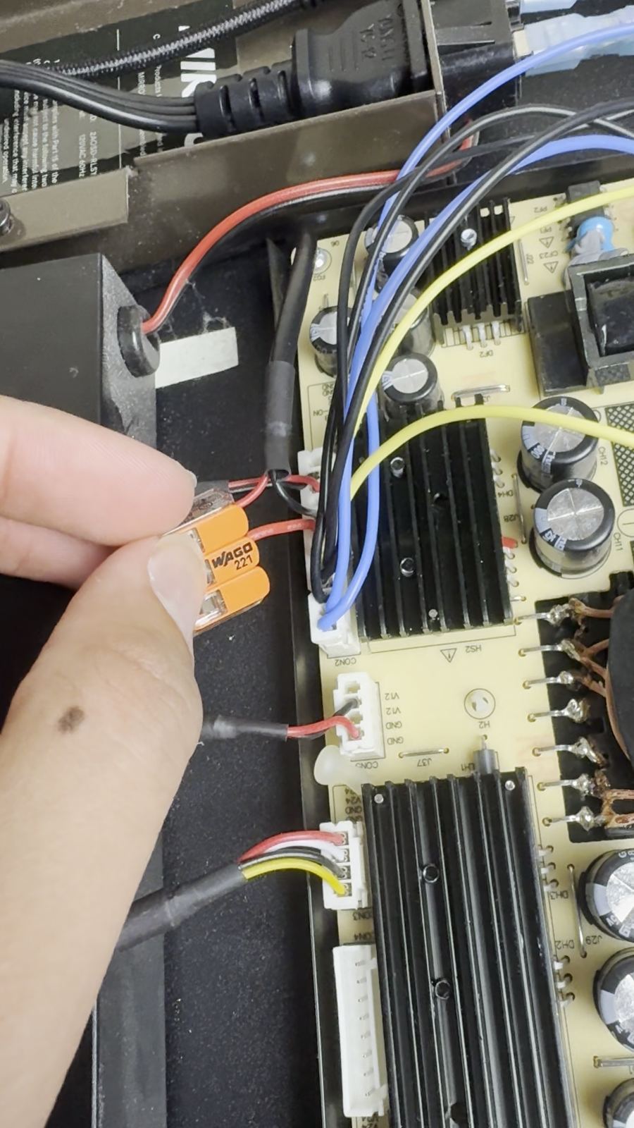
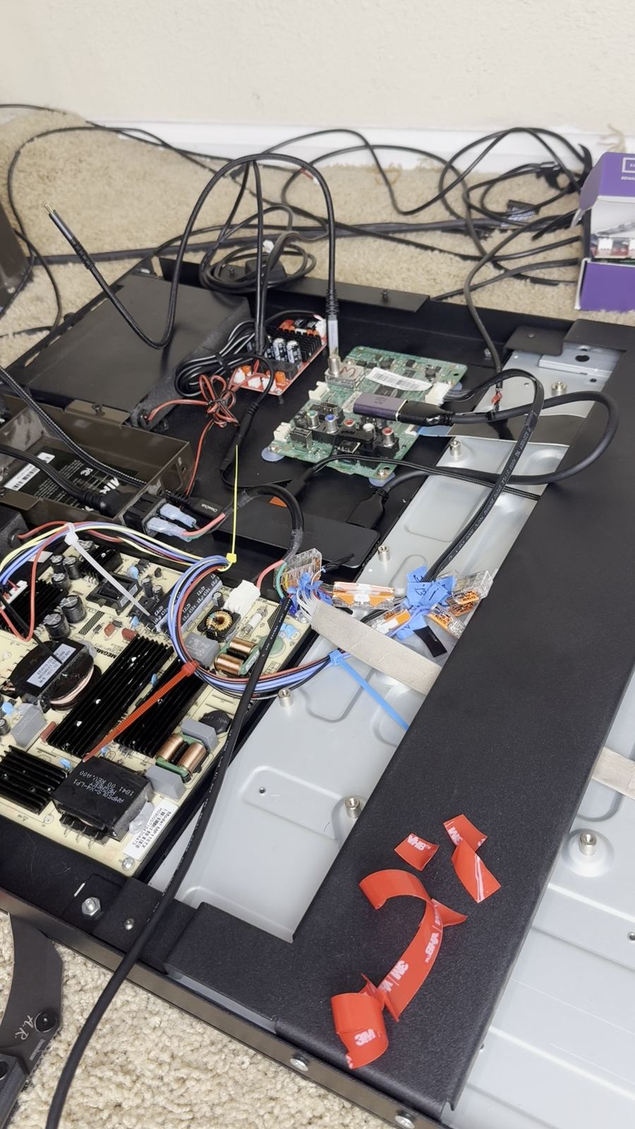
- TV's 14-pin harness rewired into the Mirror's Megmeet PSU via WAGOs
- Laptop on one USB-C: HDMI, camera, audio
Episodes
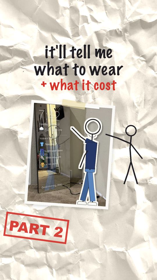
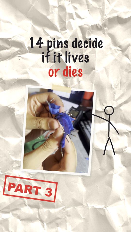
Parts
Samsung TV board$19.99
14-pin harness$12.00
LVDS ribbon$28.49
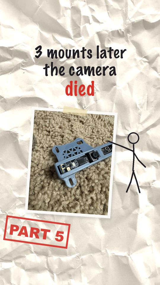
camera$58.99
IR receiver + remote$14.04
crimp kits + WAGOs$55.93
cables + adapters$23.48
parts$212.92
mirror $1,500$150.00
| Part | Job |
|---|---|
| Samsung BN94-06778C | Drives the panel, HDMI in |
| 14-pin harness | Board power, cut and wired to the Megmeet |
| 51-pin LVDS BN96-28391N | Video to the T-con i |
| Innomaker U30CAM-4K-S1 | 4K UVC camera, not wide-angle |
| WAGO 221 | Every power join |
| XH + PA crimp kits | New PSU and IR pins |
| USB-C hub, 10 ft USB-C, 1 ft HDMI | One cable to the laptop |
| Right-angle HDMI + aux | Low clearance under the board |
Signal path
video / USBaudioDCAC
Wiring
Rails
Source → WAGO → load. Everything except the camera lives in the bottom bay.
12 V5 Vstandby24 VGNDenabledimsignalunused (dashed)
CON2 1–2A · 12 VCN201 7, 9, 11, 12, 13
CON2 3–5B · GNDCN201 5, 6, 8
CON2 6–7C · 5 VCN201 1, 3
CON2 8 + rockerD · standbyCN201 4
CON3 V24 ×2E · 24 VCON101 1–5
CON3 GND ×2F · BL GNDCON101 6–10
CN201 10G · BL enableCON101 12
CN201 14H · BL dimCON101 14
Connectors
Tap a photo for full size.
Megmeet CON2
13-pin XH 2.5 mm · PSU board KB-5150 · silkscreen order, slot 1 at the top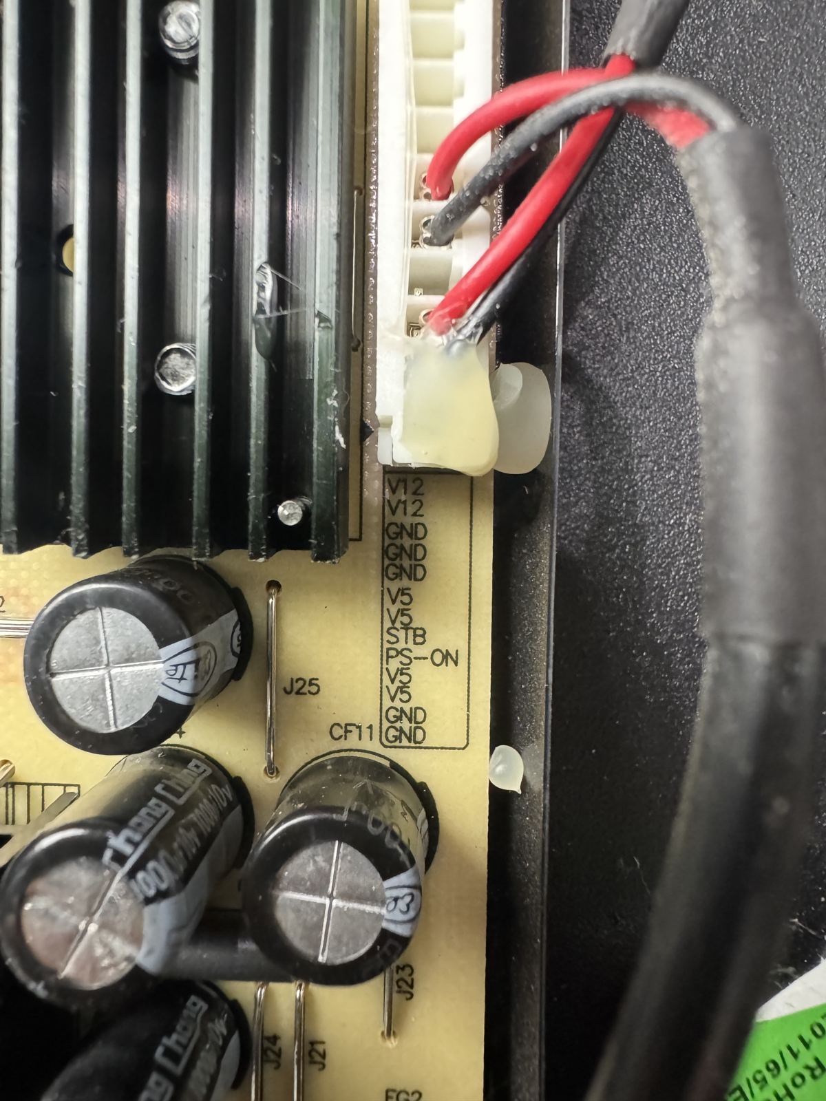
1V12→ A2V12→ A3GND→ B4GND→ B5GND→ B6V5→ C7V5→ C8STB→ D9PS-ON↔ rocker10V511V512GND13GND
| Slot | Silk | Stock wire went to | Now | WAGO |
|---|---|---|---|---|
| 1 | V12 | Android board | new blue | A |
| 2 | V12 | Android board | new blue | A |
| 3 | GND | Android board | new black | B |
| 4 | GND | Android board | new black | B |
| 5 | GND | Android board | new black | B |
| 6 | V5 | Android board | new yellow | C |
| 7 | V5 | Android board | new yellow | C |
| 8 | STB | rocker lead (red) | new 10 cm lead | D |
| 9 | PS-ON | rocker lead | stock, untouched | – |
| 10 | V5 | mic board | unused | – |
| 11 | V5 | mic board | depinned | – |
| 12 | GND | mic board | depinned | – |
| 13 | GND | mic board | unused | – |
- Rocker switch bridges 8 STB to 9 PS-ON: rocker on pulls PS-ON up and the main rails start.
- Slot 8's rocker lead was too thin for a WAGO, so it was depinned rather than cut. New lead in slot 8, rocker lead and the STB jumper share WAGO D.
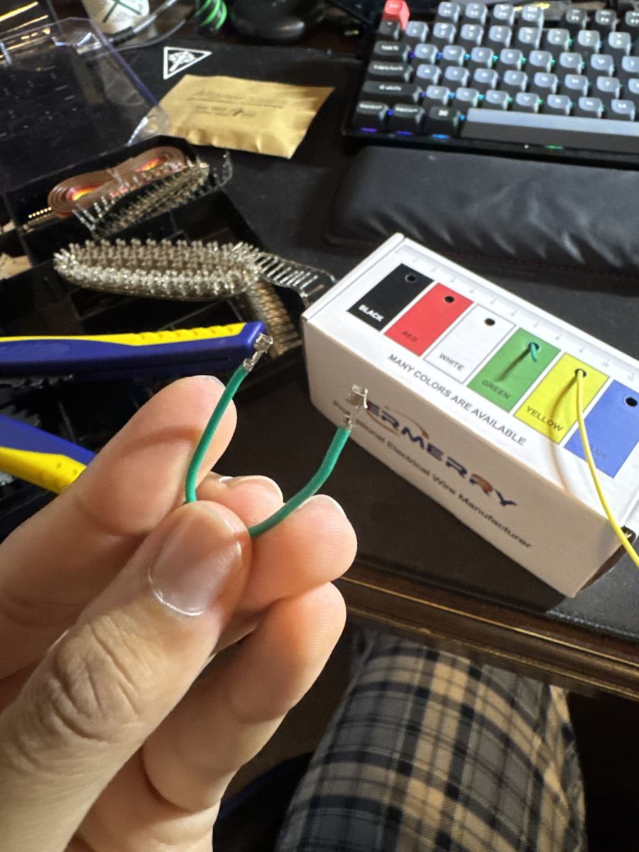
- New leads: 22 AWG, short XH pins, CON2-to-board + 20 cm. Blue = 12 V, black = GND, yellow = 5 V.
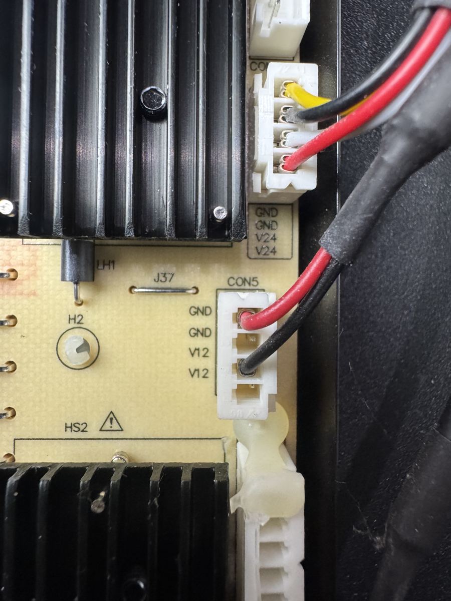
Megmeet CON3 + CON5
24 V backlight rail · 12 V amp rail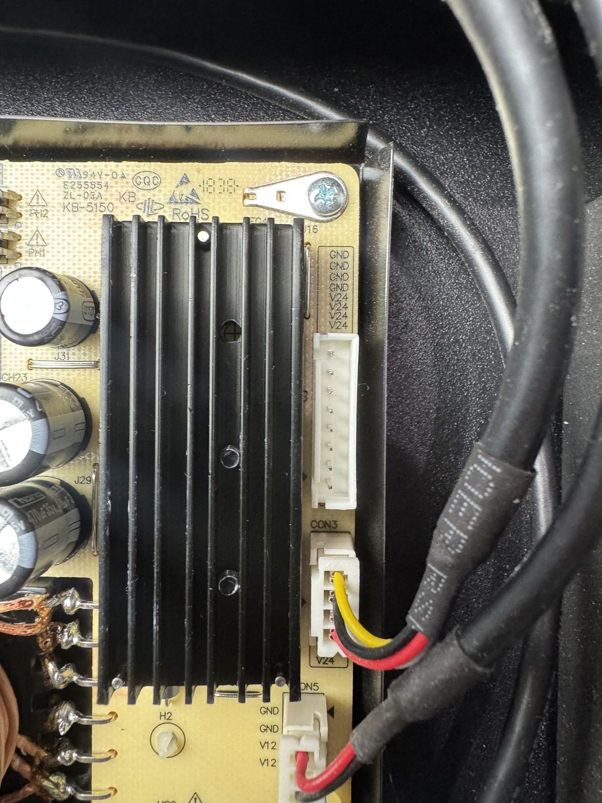
1234
CON3
1234
CON5
| Header | Pins | Silk | Stock | Now |
|---|---|---|---|---|
| CON3 | 4 | V24 ×2 GND ×2 | Cut off the Android-end plug | E (24 V), F (GND) |
| CON5 | 4 | GND ×2 V12 ×2 | Amp VCC / GND | stock cable, untouched |
| 8-pin header | 8 | GND ×4 V24 ×4 | empty | – |
- Before cutting CON3: black probe on CON2 slot 3, beep each CON3 wire. The 2 GND wires beep, the 2 V24 wires don't.
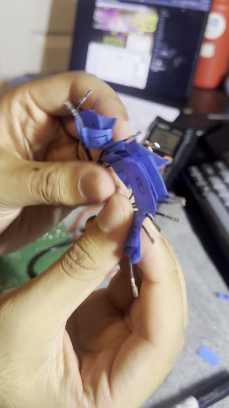
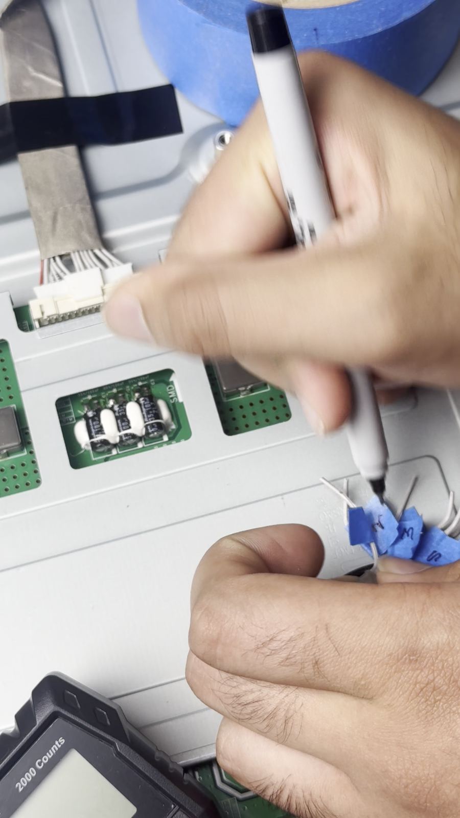
- Pin order inside CON3 isn't silkscreened per pin. Tag from the beep test, not from wire colour.
Samsung CN201
14-pin power in · BN94-06778C (UN39FH5000FXZA) on BN97-07695D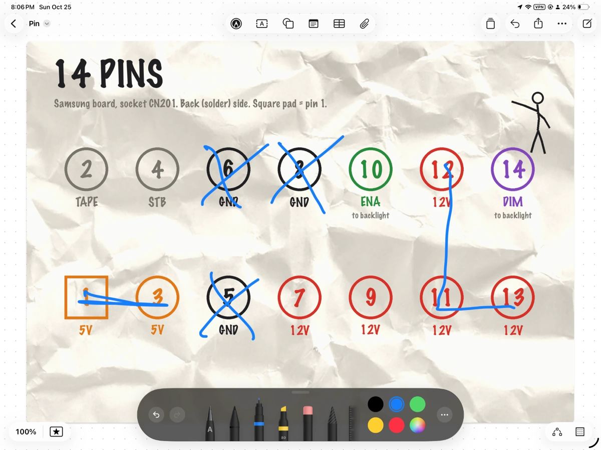
2468101214
135791113
solder side · square pad = 1 · odd row toward the board edge
| Pin | Samsung net | Role | Thread #i | WAGO | Board unplugged |
|---|---|---|---|---|---|
| 1 | B5.3V | 5 V | 13 | C | 5 V |
| 2 | SW_PW | unused | 14 | tape off | 0 V |
| 3 | B5.3V | 5 V | 11 | C | 5 V |
| 4 | A5.3V | standby 5 V | 12 | D | 5 V |
| 5 | GND | GND | 9 | B | 0 V |
| 6 | GND | GND | 10 | B | 0 V |
| 7 | B13VS_AMP | 12 V | 7 | A | 12 V |
| 8 | GND | GND | 8 | B | 0 V |
| 9 | B13VS_AMP | 12 V | 5 | A | 12 V |
| 10 | SW_INV | BL enable | 6 | G | 0 V* |
| 11 | B13VS_PW | 12 V | 3 | A | 12 V |
| 12 | B13VS_PW | 12 V | 4 | A | 12 V |
| 13 | B13VS_PW | 12 V | 1 | A | 12 V |
| 14 | PWM_DIM | BL PWM dim | 2 | H | 0 V* |
- Groups, beeped with the harness on the board, unpowered: 5, 6, 8 to the HDMI shell · 11–12–13 · 7–9 · 1–3.
- Pins depinned (latch pressed with a pick), not cut. Pin 1's wire snapped on extraction and was re-crimped.
- *10 and 14 are outputs from the board, so they read 0 V until it's plugged in.
Backlight CON101
14-wire foil-shielded cable · LED driver LJ63-15536A on the panel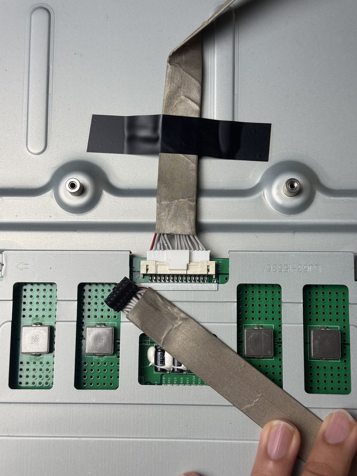
1234567891011121314
as seen on the LED driver: pin 1 on the right, red wire = 14
| Wire | Function | Role | WAGO |
|---|---|---|---|
| 1 | VIN | 24 V in | E |
| 2 | VIN | 24 V in | E |
| 3 | VIN | 24 V in | E |
| 4 | VIN | 24 V in | E |
| 5 | VIN | 24 V in | E |
| 6 | GND | GND | F |
| 7 | GND | GND | F |
| 8 | GND | GND | F |
| 9 | GND | GND | F |
| 10 | GND | GND | F |
| 11 | NC | unused | tape off |
| 12 | ENA | enable | G |
| 13 | NC | unused | tape off |
| 14 | EXT_DIM | dim | H |
- Cut behind the Android-end plug, foil trimmed back 6 cm.
- Each wire beeped to the CON101 legs and flagged 1–14 with tape before anything else.
- VIN and GND pair up into WAGO ports: 1+2, 3+4, 5 and 6+7, 8+9, 10.
LVDS ribbon
video, board to panel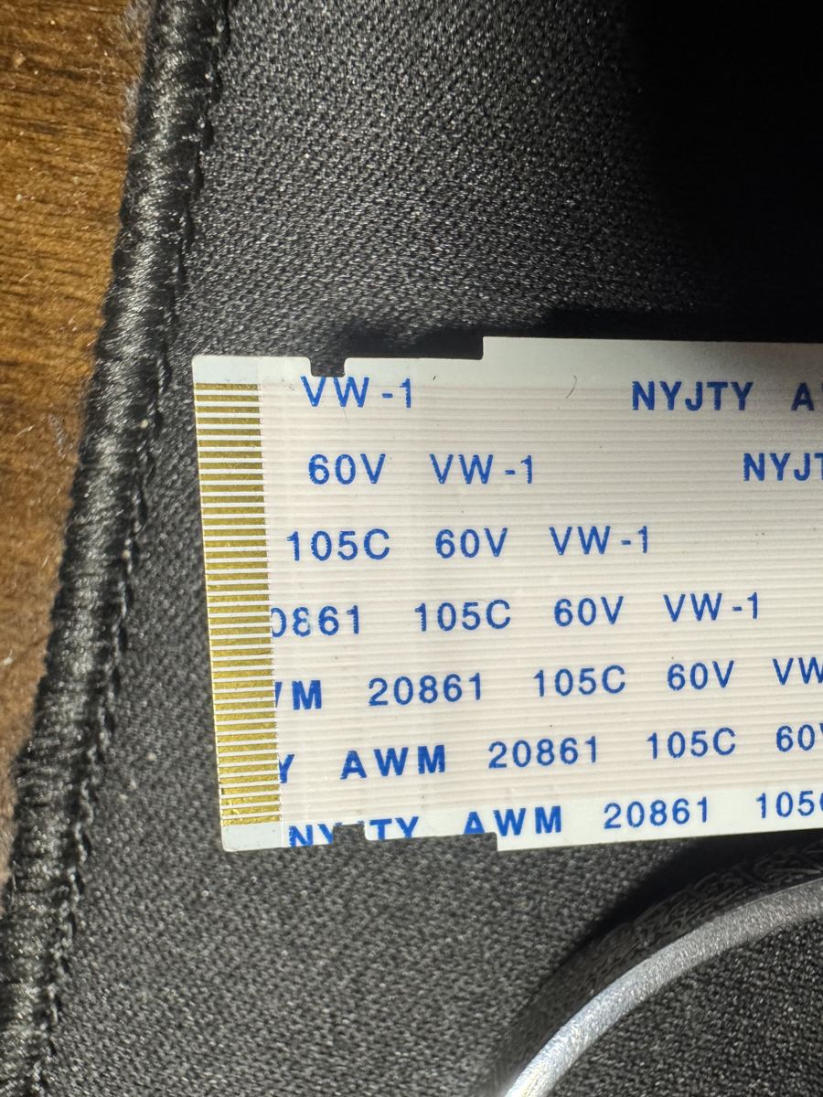
CN1301 (FHD)T-con PANEL
51-pin FFC, contacts span ~25 mm
| Board end | CN1301_FHD (blue stiffener end). CN1302_HD unused |
| Panel end | T-con socket marked PANEL |
| Cable | BN96-28391N, from a Samsung UN75F6300 |
| Length | needs ~750 mm board-to-T-con. Listing estimate ~80 cm from the 23 mm width |
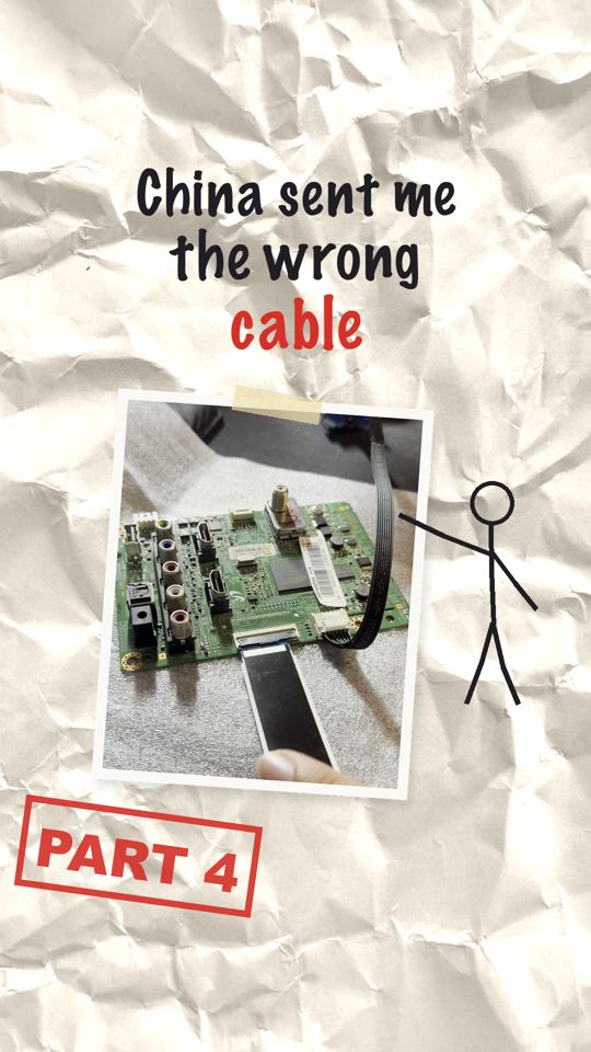
| Wrong one | first cable: 41-pin, 500 mm, sold as 51-pin |
- Count contacts before inserting. 41 vs 51 is easy to miss: the narrow one still clicks in, flush to one end.
Audio: CN301 to amp
headphone out → 2-ch class-D amp (12 V from CON5)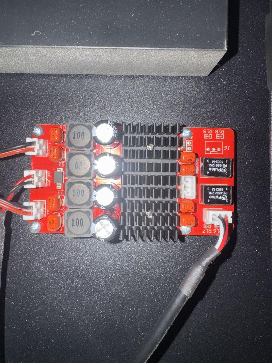
TRS
3.5 mm into CN301
LRG
amp 3-pin XH in
| 3.5 mm | Signal | Lands on |
|---|---|---|
| Tip | Left | amp L |
| Ring | Right | amp R |
| Sleeve | GND | amp GND |
- Stock path was Megmeet → mic board → amp. Mic board removed; the old 3-pin XH input cable was cut and re-terminated onto an aux pigtail.
- Board clearance is ~3.4 mm, so the plug goes in through a right-angle adapter. The first 90° aux was too bulky; use a low-profile one without a mic ring.
- First build gave no sound and was remade. Beep tip/ring/sleeve before crimping.
IR receiver: CN702 (optional)
TSOP4838 · legs left to right with the dome facing you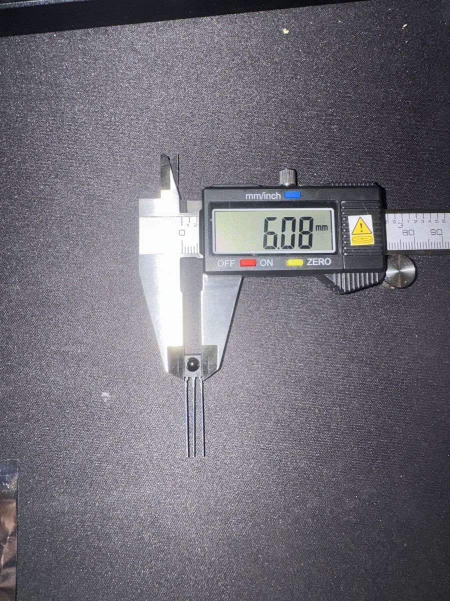
123456
PA 2.0 6-pin into CN702
| Pin | Signal | From |
|---|---|---|
| 1 | OUT | TSOP4838 left leg |
| 2 | GND | middle leg |
| 3 | VS | right leg |
| 4–6 | keys | unused |
- Body 6.08 × 6.86 × 3.75 mm, 5.93 mm with dome. Mount: IR mount.
- My build read OL at the plug and was dropped. The board powers up straight to HDMI, so no remote is needed.
WAGO ports
One port per box. "7+9" = two wires twisted into one port.
A · 12 V221-415 · 5-port · by the board
1CN201 7+92CN201 11+123CN201 134CON2 1 blue5CON2 2 blue
B · GND221-415 · 5-port · by the board
1CN201 5+62CN201 83CON2 3 black4CON2 4 black5CON2 5 black
C · 5 V221-413 · 3-port · by the board
1CN201 1+32CON2 6 yellow3CON2 7 yellow
D1 · standby221-413 · 3-port · beside CON2
1CON2 8 new lead2rocker lead3STB jumper
D2 · standby221-412 · 2-port · by the board
1STB jumper2CN201 4
E · 24 V221-415 · 5-port
1CON101 1+22CON101 3+43CON101 54CON3 V245CON3 V24
F · BL GND221-415 · 5-port
1CON101 6+72CON101 8+93CON101 104CON3 GND5CON3 GND
G · BL enable221-412 · 2-port
1CON101 122CN201 10
H · BL dim221-412 · 2-port
1CON101 142CN201 14
Stock: 4× 5-port, 8× 3-port, 8× 2-port. Power uses 4× 5-port, 2× 3-port, 3× 2-port.
Checks
1 · Continuity, unpowered
| Probe | To | Expect |
|---|---|---|
| CN201 pad n | harness wire n | beep, all 14 |
| CN201 5, 6, 8 | HDMI shell | beep |
| CN201 11 | 12, 13 | beep |
| CN201 7 | 9 | beep |
| CN201 1 | 3 | beep |
| CON2 slots | silkscreen nets | match |
| CON3 wires | CON2 slot 3 | 2 beep (GND), 2 open |
| CON101 legs | cut wire ends | 1:1, flag each |
| A, C, E | B / F | open (no short) |
2 · Voltage, board unplugged
| + probe | − probe | Expect | Read |
|---|---|---|---|
| CN201 7, 9, 11, 12, 13 | B | 12 V | 12.07 |
| CN201 1, 3, 4 (STB) | B | 5 V | 5.3 |
| CN201 2, 5, 6, 8, 10, 14 | B | 0 V | 0.01 |
| E | F | 24 V | – |
| CON5 V12 | CON5 GND | 12 V | – |
Wall on, rocker on, paper under the bay. Over ±10%: power down, find it, don't plug in.
Wire + crimp spec
| Wire | Fermerry 22 AWG stranded. Blue 12 V, black GND, yellow 5 V |
|---|---|
| CON2 pins | JST XH 2.5 mm, short pins, strip 2.5 mm, tug-test each |
| IR plug | PA 2.0 mm 6-pin |
| WAGO strip | 11 mm. Thin harness wire: strip 22 mm, fold in half |
| WAGO type | 221-41x lever (24–12 AWG). Not 221-2401 inline (20–12 AWG, won't grip 22) |
| Lengths | CON2 → board spot + 20 cm. Nothing runs full height; camera is USB |
| Count | ~50 crimps total |
| Insulation | WAGOs taped to plastic, flat. Paper under the board for first power-on |
Build steps
0 / 0
i
Teardown
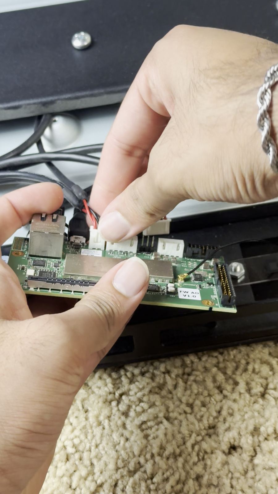
Map the harness
Repin CON2
Number the backlight cable
WAGOs
Voltage check
Mount + first light
Audio + USB-C
3D prints
OpenSCAD · Bambu P1S · PLA on textured PEI, 55 °C, no supports
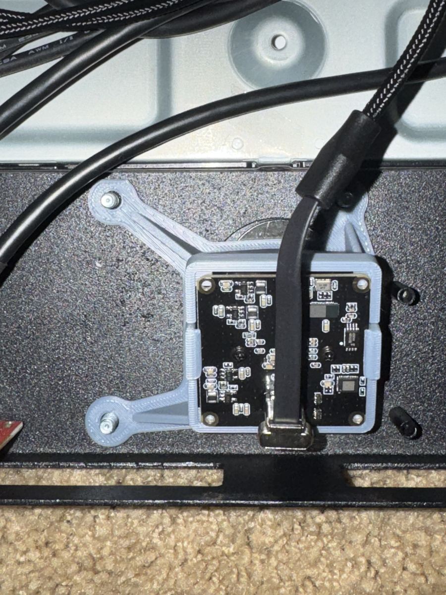
Camera mount v2
- Fits
- 38 mm board, 20° down, snap-in
- 1 h 55, brim
- Hardware
- 3× M4 nuts
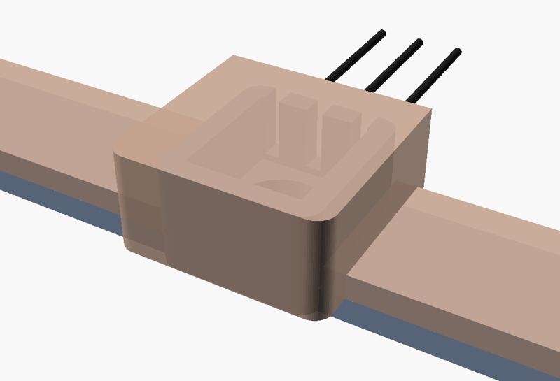
IR receiver mount i
- Fits
- TSOP4838, 74 mm stud pitch
- 34 min, one plate
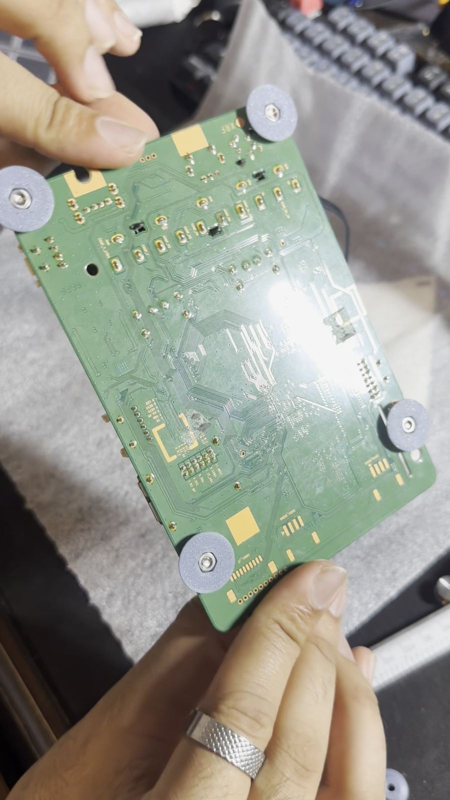
Board feet
- Fits
- BN94-06778C corner holes, 3.4 mm tall
- Hardware
- 4× M3×4, washer, nut; VHB
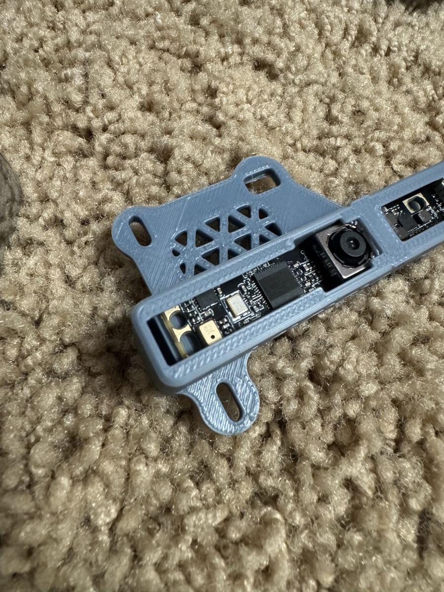 retired
Camera mount v1
- Fits
- Arducam 16MP USB stick
Board-to-panel matching from the olm3ca/mirror thread.